NX CAD PRODUCT DESIGN
Accelerate Innovation with Leading-Edge NX CAD 3D Product Design Software.
The increasing complexity of products, development processes and design teams challenges you to find new tools and methods to deliver greater innovation and higher quality at lower cost. Siemens NX 3D product design CAD software delivers power, efficiency and cost savings that extend beyond the design process to all phases of product development.
FLEXIBILITY AND POWER FOR THE TOUGHEST DESIGNS
NX CAD mechanical product design software delivers comprehensive modelling, enabling you to use the most productive approaches interchangeably – from explicit solid and surface modelling to parametric and direct modelling.

NX CAD Software helps you to use any modelling approach that fits your design challenge freely. With the industry’s most powerful and versatile CAD modelling tools, you can create and edit geometry with incredible speed and flexibility.
- Comprehensive 3D Modeling Software
- Modular Product Design for Complex Components
- Intuitive, Discoverable and Configurable User Interface
- ASSEMBLY DESIGN
CREATE AND MANAGE ASSEMBLY CAD MODELS OF ANY SIZE OR COMPLEXITY WITH NX CAD
Siemens NX provides the most powerful CAD assembly design tools available. NX provides advanced assembly management and navigation for the most complex assemblies by supporting both top-down and bottom-up design techniques.

NX provides the most powerful CAD assembly design tools available. Supporting both top-down and bottom-up techniques, NX helps you manage and navigate assembly models and keep your team organized and on track.
- Performance for Massive Assemblies
- Accelerate Assembly Design, Improve Quality
- Digital Mock-up in the Assembly Design Environment
SHEET METAL DESIGN
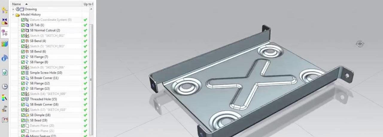
Efficiently Design and Manage Sheet Metal Components using familiar terminology and workflows. NX CAD Software helps you create sheet metal parts based on the knowledge of material properties and manufacturing processes.

NX sheet metal design tools incorporate material and bending information, enabling the model to represent the formed component and flattened blank shapes.
NX sheet metal design software incorporates material and process information in sheet metal-specific modelling features: bends, flanges, tabs, cutouts, beads, dimples, louvres, corner and edge treatments, patterns and other formable features.
You can also quickly convert solid models to sheet metal components and create metal parts enclosing other components.
TEMPLATE-BASED DESIGN
Designing from product templates helps you accelerate design, standardize product design processes, and maximize the time and cost savings of re-use. With NX CAD, you can quickly create templates from existing designs and easily reuse them for new designs.
Reusing design information and process knowledge helps reduce costs, increase innovation, and boost efficiency in product design. NX CAD supports your reuse strategies with template-based design.
This enables you to readily use parametric product models as templates for new designs, incorporating your product and process knowledge within the template to dramatically reduce the time and effort required to develop product variants. Click here for more details.
Fiberism
The end-to-end design and manufacturing solution for composite parts
The nature of fibre-reinforced plastic products requires rapid changes in how analysis, design and manufacturing are traditionally performed. Unravel the complexities of these materials with the Fibersim software portfolio.

Experience a concurrent engineering process where analysis and design are performed in the context of the manufacturing process, which is key to developing optimal designs. The open architecture of Fibersim provides a specialized engineering environment to create a composite digital twin in NX.
Composite Engineering and Manufacturing
Managing composite complexity with specification-driven design and manufacturing
The benefits of composite materials derive from the ability to indeed engineer the performance of the part by varying thicknesses, fibre angles, material types, and part shapes.
These myriad design variables produce inherent complexity unique to composite parts and link the part geometry, material behaviour and manufacturing process.
Only by mastering the intersection of these three characteristics can the full potential of composites be unlocked.
Fibersim provides the key with flexible design methodologies that capture the specifications from analysis and efficiently flow them through the manufacturing process to produce an optimized composite part that can be produced on a budget.
Composite Design & Analysis
Efficiently adapt to changes while providing an accurate simulation of the as-manufactured composite part.
Using Fibersim as the hub for your composite part design allows for the efficient input of requirements from CAE to create a CAD digital twin that can rapidly react to changes in shape and specification, all while providing a window onto the shop floor to ensure the producibility of your design. Design rules provide powerful automation in creating ply boundaries from minimal geometry input. Additionally, advanced sorting, filtering, and renaming capabilities provide efficient tools for navigating the complexity of modern composite parts.
Composite Design & Analysis comprises powerful features that allow you to build a custom solution. Read more about these features below.
Design Data Verification
Engineering documentation brings visibility to the composite details during verification, including drop-off profiles, ply sequence order, and ply materials. Fibersim helps automate the creation of cross sections, annotations, and core samples that are updatable as changes occur, ensuring the design is accurately reflected. Fibersim core sampling capabilities provide deeper details, such as ply thickness changes, fibre deviation, balance, and symmetry, which are invaluable in ensuring product quality. Understanding laminate weight and cost is critical to making go/no-go decisions during verification. Fibersim instantly provides the laminate weight and cost, including post-cure processes, to provide the most accurate information during review.
Assembly relationships, such as packaging and clash detection, are important for design verification. Fibersim automatically creates surface and solid representations that allow you to detect clashes between assembly components and ensure that packaging requirements are met.
Detailed Design Definition
Whether you are designing a solid airfoil with Fibersim’s Volume Fill capability, using Zone-based design to produce nested plies in a significant structural component, or leveraging Fibersim’s unique Multi-Ply approach to automate a ply-based design, Fibersim has the optimal design methodology for your part type.
Once authored, this complete composite definition can be leveraged throughout the enterprise, from flat patterns and laser-projected ply boundaries on the shop floor to 3D documentation for design reviews to accurate weights directly in Teamcenter.
Preliminary Design
Fibersim’s bi-directional Analysis Interface provides an automated exchange of stress requirements into a CAD digital twin. Even before detailing the part with design rules, preliminary weights and space claim solids can be derived from the zone definition.
Once the final ply boundaries have been defined, the true fibre orientations can be returned to stress and re-analyzed with the as-manufactured definition.
Product Producibility Simulation
Fibersim’s producibility simulation is a production-proven capability for accurate flat patterns and true fiber orientations. With the complex curvature and advanced materials of modern composites, specified orientations cannot be assumed, and having a reliable simulation of the part producibility is critical to repeatable and high-performing parts.
Fibersim can also provide a preliminary look at path-planning challenges for automated deposition.
For More Details, CLICK HERE
